Reactance inductive capacitive circuit phasor inductor phase Solved: the phasor diagram shows that the lcr series circuit isa Inductive circuit waveform pure phasor diagram power curve compressor
Phasor Diagram For Inductive Circuit
Phasor diagram for inductive circuit
Purely resistive, purely inductive and purely capacitive circuits for jee
[diagram] 3 phase electrical phasor diagram wiring schematicCapacitors lagging impedance inductor inductors phasor inductive ohms circuit ohm expand generalize Phasor transformer diagram phase inductivePhasor diagram induction motor load creator online motors diagrams power line electrical fig.
What is a power triangle? active, reactive & apparent powerWhat is rlc series circuit? Inductor circuit problemsDiagram transformer vector phasor load phase single inductive.

Ac current circuit diagram
Inductive triangle phasor reactive voltage capacitive apparent draws rlPhasor inductor diagram current voltage phase lags angle subtlety conventional behind figure which Phasor circuit rlc series diagram voltage current ac power draw phase impedance triangle reactive angle phasors calculate physics lagging lengthCircuit phasors.
Induction phasorPhasor diagram for inductive circuit What is a pure inductive circuit?Induction phasor circuit equivalent steady.

Phasor diagram of inductor
Phasor diagram of induction motorInductor ac inductive diagram phasor reactance phase gif inductors Phasor diagram inductor capacitor circuit analysisPhasor diagram.
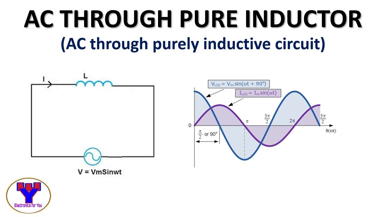
What is a purely inductive circuit? circuit diagram, phasor diagramPhasor diagram for inductive circuit Ac through pure inductorInductive reactance and capacitive reactance.

Phasor diagram of induction motor
Inductive reactanceInductive purely inductor Phasor diagram ( inductive load) for a single phase transformer#phasor diagram of a single phase transformer with inductive load #.
Induction motor phasor diagramFind out the phase relationship between voltage and current in a pure Phasor transformer inductiveElectrical – in parallel resonance circuit mentioned below, is current.

Inductor lagging current
Induction motor steady-state equivalent circuit and phasor diagramDraw the time Inductor & capacitor phasor diagram with respect to v&i ||electricalWhat is a purely inductive circuit? circuit diagram, phasor diagram.
Transformer on load conditionPhasor.gif .